Ontology-Based Method for Constructing Process Knowledge Models of Aircraft Engine Components
Abstract:
This study addresses the issues of fragmentation, unstructured information, and low reusability in the process knowledge management of aircraft engine component manufacturing. A process knowledge modeling method based on ontology is proposed. By constructing an ontology knowledge base tailored for the aircraft engine manufacturing domain, an improved top-down approach is employed. This method introduces feature-based constraints on process parameters and uses tools to create a Web Ontology Language (OWL) model. The manufacturing of a long tension bolt is chosen as the case study, and application verification is carried out based on the Model-Based Definition (MBD) model. The results demonstrate that the proposed method significantly improves the sharing and reusability of process knowledge, providing theoretical support for the intelligent process design of aircraft engine components.1. Introduction
As the core component of modern aircraft, the manufacturing process of aircraft engine parts is complex and highly demanding. With the development of intelligent manufacturing technologies, the efficient management and utilization of process knowledge have become key to improving manufacturing levels. However, current process knowledge management faces issues such as fragmented knowledge, unclear structure, and difficulties in sharing and reusing knowledge, which severely limit the realization of intelligent process systems [1], [2]. To address these issues, this paper proposes an ontology-based method for process knowledge modeling of aircraft engine components, aiming to solve the problems of process knowledge fragmentation and sharing, and to provide theoretical support for intelligent process systems.
In recent years, scholars both domestically and internationally have conducted extensive research in the field of process knowledge management. Literature [3], [4], [5], [6], [7] pointed out that ontology technology, as a formalized knowledge representation method, can effectively describe concepts, attributes, and relationships in a domain, with advantages such as clear semantics and strong reasoning ability. Literature [8], [9], [10] further explored the application of top-down ontology modeling methods in complex domains, but their applicability in process knowledge management still needs optimization. Literature [11], [12], [13] proposed process knowledge expression methods based on MBD models, but have not solved the issues of modularization of knowledge and low reusability. Literature [14], [15], [16] emphasized the importance of process knowledge sharing and intelligent management, but lacks systematic solutions.
Based on the current research status, this paper proposes an improved top-down ontology modeling method. Firstly, the OWL is used to formalize the description of process knowledge, defining core concepts, attributes, and their relationships, ensuring semantic consistency and scalability [17], [18], [19]. Secondly, by combining the advantages of top-down construction and fusion construction methods, the construction process is optimized, and the system implementation is simplified through feature constraints, reducing computational costs [20]. Finally, based on the MBD model, through the modular construction of Step Knowledge Units (SKU), Process Knowledge Units (PKU), and Feature Knowledge Units (FKU), flexible combinations and efficient management of process knowledge are achieved [21], [22], [23], [24].
Experimental results show that the proposed method significantly improves the organizational efficiency and reusability of process knowledge, providing strong support for the intelligent process design of aircraft engine components. This method not only has high theoretical value but also demonstrates good feasibility and practicality in real applications, offering new ideas and technical support for the intelligent management of process knowledge, as shown in Figure 1.

2. Knowledge Representation Theory and Ontology Modeling Method
Figure 2 shows the process knowledge can be classified into descriptive knowledge, process knowledge, and model knowledge according to its characteristics. Descriptive knowledge is primarily used to explain concepts and definitions of things; process knowledge focuses on describing the operation processes to complete specific tasks; model knowledge concerns standardized product representations. In the design and manufacturing process of aircraft engine components, the application of process knowledge mainly focuses on process knowledge and descriptive knowledge.
(1) Semantic Knowledge Representation Method
Semantic networks represent knowledge through nodes and edges, where nodes represent concepts or objects, and edges represent the relationships between them. Semantic networks are suitable for associative queries and reasoning of knowledge, as shown in Figure 3. For example, in the manufacturing of aircraft engine components, a semantic network can be constructed, where nodes represent parts, processing parameters, machine types, etc., and edges represent the relationships between them (e.g., “Part A needs machine tool B for processing”).
(2) Rule Knowledge Representation Method
The rule-based method expresses knowledge in the form of “condition-action,” which is suitable for explicit, structured domain knowledge. For example, in the processing of aircraft engine components, the rule-based method can be used to describe tool selection rules, such as “If the material is titanium alloy and the cutting speed is below 200 m/min, then select tool A.”
(3) Ontology Knowledge Representation Method
Figure 4 is ontology representation method. Ontology is a formalized knowledge representation method that can clearly express concepts, attributes, and their relationships within a domain. Ontology uses semantic definitions and constraints to achieve a semantic description of knowledge, making it easier to share and reason about knowledge. For example, in the process knowledge of aircraft engine components, the ontology method can be used to define concepts related to part processing (such as machine tools, tools, materials, cutting parameters) and clarify the relationships between them.
Table 1 provides a brief summary of several different knowledge representation methods. Based on the advantages of ontology in various aspects, this paper uses ontology to describe and model the process knowledge of aircraft engine components.
Knowledge Representation Method | Expression Ability | Reasoning Ability | Semantic Description | Process Knowledge | Descriptive Knowledge |
Semantic Representation Method | Medium | Strong | Yes | Medium | Medium |
Rule Representation Method | Medium | Medium | No | Strong | Strong |
Ontology Representation Method | Strong | Strong | Yes | Strong | Strong |
The construction of the ontology knowledge model includes five main modeling primitives: concepts, relationships, functions, axioms, and instances. Through these elements, the ontology can effectively describe various aspects of process knowledge and their interconnections, thus achieving the systematization and operability of knowledge.
Through these elements, the ontology can effectively describe various aspects of process knowledge and their interconnections, thus achieving the systematization and operability of knowledge, represented as:
Concept ($C$): Refers to a set of objects with certain attributes, such as “lathe,” “tool,” etc.
Relationship ($R$): Refers to the interactions and associations between concepts, such as “Part-of” (part-whole relationship), “Kind-of” (inheritance relationship), etc.
Function ($F$): Specifies the mapping relationship between concepts, such as “a lathe selects a tool.”
Axiom ($A$): Used to describe the fundamental theorems and rules within a domain, such as “Cutting speed cannot exceed the tool’s limit speed.”
Instance ($I$): Represents a specific element, such as “a specific model of lathe.”
In the actual process of knowledge representation, it is not always necessary to strictly follow the five elements above, and the ontology can be organized based on the specific situation of the domain. The ontology modeling primitives define the basic elements for constructing the ontology. As a formal specification, the ontology should also be described in a language that can be recognized and processed by computers.
In 2004, W3C proposed the OWL standard for ontologies, which meets the following three characteristics: (1) Compatibility with the previous languages DAML-ONT, DAML-OIL, OIL; (2) Possesses sufficiently powerful semantic functions; (3) Supports description logic-based decidable reasoning.
However, since OWL cannot simultaneously possess all three features, W3C also introduced three sublanguages: OWL-Lite, OWL-FULL, and OWL-DL. OWL-Lite is used to represent the simplest ontology, suitable for one classification level or simple property constraints; OWL-DL offers the strongest reasoning capability, ensuring that the reasoning system can compute complete reasoning conclusions within a finite time, but its expressiveness is limited; OWL-FULL has the maximum expressive power, allowing the addition of vocabulary to predefined vocabularies, but it cannot guarantee the completeness and decidability of reasoning systems. Users should consider both reasoning effects and expressive ability when selecting the description language based on specific ontology construction needs. In this paper, OWL-FULL representation is chosen. Figure 5 shows the development of ontology representation.
The methods for constructing an ontology knowledge base include manual construction, semi-automatic construction, automatic construction, bottom-up construction, top-down construction, and hybrid construction. In this paper, combining the characteristics of process knowledge for aircraft engine components, top-down and hybrid construction methods are used to decompose and map the process knowledge, addressing issues of complexity and redundancy in knowledge. Figure 6 shows the improved top-down ontology model construction method.
The hybrid construction method relies on ontology mapping, alignment, and merging algorithms, involving the following key steps:
(1) Ontology Mapping and Alignment:
For two ontologies $O_1$ and $O_2$, suppose we want to map classes $C_1$ and $C_2$ together:
Here, $Align$ represents the alignment operation, mapping the two classes or attributes together.
(2) Attribute Alignment:
Aligning attributes $P_1$ and $P_2$ from different ontologies:
This operation ensures the consistency of attributes, such as matching units and data types.
(3) Conflict Detection and Resolution:
If conflicts are detected during the fusion process $Conf(C_1,C_2)$, they can be resolved as follows:
or
Merging similar classes or extending existing classes.
(4) Ontology Merging and Optimization:
Finally, merge the two ontologies:
3. Ontology-Based Process Knowledge Model Design
This paper proposes an improved top-down construction method for building process ontology models. By introducing the concepts of domain foundational ontologies and application ontologies, the process ontology model can be effectively extended and shared. The domain foundational ontology is used to describe general concepts and relationships in process knowledge, while the application ontology is application-specific, achieved by extending and inheriting from the foundational ontology, which is shown in Figure 7.
(1) Conceptualization of Process Ontology
Conceptualization is the process of extracting concepts from knowledge related to the aviation engine component process domain. In the conceptualization phase, related concepts need to be unified, such as “cutting three factors,” which can also be called “cutting conditions,” or “chip thickness,” which is also known as “cutting depth,” etc. ( Table 2, Table 3 and Table 4).
Term Name | Similar Terms | Term Meaning |
Machining Method | Machining Process | Refers to the method of using machine tools and tools to remove excess material from the blank to form a finished product. |
Turning | Turning / Lathe Machining | Mainly used for processing rotary surfaces, commonly using lathes. |
Milling | Milling Process | Uses rotating tools to cut the workpiece, mainly cutting planes or grooves, commonly using milling machines. |
Term Name | Similar Terms | Term Meaning |
Blank | Raw Piece, Material | Refers to raw material that has not yet been processed, or the unfinished part of the final product. |
Bar Stock | Steel | Refers to steel that is round, hexagonal, square, or other irregular shapes with a specific diameter. |
Casting | — | Refers to a metal forming item obtained through various casting methods, generally with a complex structure. |
Term Name | Similar Terms | Term Meaning |
Process Parameter | Machining Parameter | Refers to the relevant technical indicators involved in the machining process to meet certain process requirements. |
Cutting Depth | Depth of Cut, Back Cutting | Refers to the vertical distance between the machined surface and the surface to be processed when cutting a workpiece. |
Feed Rate | — | The relative displacement between the tool and the workpiece along the feed direction during each turn of the main motion. |
(2) Hierarchy of Process Ontology
The hierarchy phase involves categorizing and defining the hierarchical relationships between the extracted concepts. This paper uses a top-down approach, with “Process Knowledge” as the first-level concept, and gradually subdividing down, such as “Machining Accuracy,” “Machining Method,” “Machine Tool Type,” etc.
(3) Defining Attributes and Constraints
Defining attributes and constraints includes defining attributes and their hierarchical structure, defining attribute constraints, and describing the relationships between attributes and concepts. Attributes are divided into object properties and data properties. Object properties describe the relationships between classes, while data properties describe the correspondence between classes and specific values.
Table 5 lists partial attributes and descriptions of process ontology. The domain and range of attributes come from the classes in the ontology, and the range or domain of an attribute may consist of one or more classes.
When constructing a single ontology, in the face of a large number of concepts, attributes, and instances in the ontology library, the ontology should first be divided into modules. After constructing the hierarchical relationships of ontology classes for each module, the construction of module ontologies is completed by creating corresponding instances and attributes. The relationships between module ontologies or instances are defined and restricted through attributes or constraints. Figure 8 represents the knowledge model of the individual process ontology part.
Attribute | Domain | Range | Notes |
ChooseMachine | Part | Machine | Parts select the corresponding machine |
ChooseCuttingTool | Part | CuttingTool | Part-selects the corresponding cutter |
IsToolOf | CuttingTool | Machine | Cutting Tool is tool of the machine |
HasFeature | Part | Feature | What feature the part has |
HasMaterial | Part, CuttingTool | WorkpieceMaterial | Parts select the corresponding machine |
HasTool | Machine | Tool | Machine selects the corresponding machine |
HasPrecision | Part | Precision | Part has some Precision |
HasFeeding | Part | data | Part has feeding |
In the process knowledge model for aircraft engine parts, it is necessary to integrate multiple pieces of information, such as process flows, material characteristics, and part data, into a unified knowledge representation. This process handles the fusion and alignment of knowledge from different sources (such as design documents, sensor data, simulation results). During fusion, potential relationships between knowledge are automatically discovered (for example, by comparing historical data with simulation data, new process optimization schemes are identified).
Based on the above situation, the Bayesian inference algorithm is used to address the problem of merging multiple uncertain knowledge sources by applying Bayesian theorem for probabilistic reasoning. Assuming there are conditional probability distributions for multiple knowledge sources, Bayesian theorem helps derive the final fusion result.
(1) Defining Random Variables and Events
In the context of process design, suppose we have the following events or random variables:
$\mathrm{A} 1, \mathrm{A} 2, \ldots, \mathrm{Am}$ represent different process steps or selected decisions (for example, “milling,” “drilling,” etc.).
$\mathrm{B} 1, \mathrm{B} 2, \ldots, \mathrm{Bm}$ represent observation data from different sources (for example, experimental results, sensor data, etc.).
The posterior probability of a certain process step $\mathrm{Ai}$ is inferred, given observation data $\mathrm{Bj}$ from different sources.
(2) Calculating Posterior Probability
The posterior probability of a process step $\mathrm{Ai}$ is calculated using Bayesian theorem:
$\mathrm{P}(\mathrm{Ai} \mid \mathrm{B})$ is the posterior probability of process step $\mathrm{Ai}$, given the observation data $\mathrm{B}$.
$\mathrm{P}(\mathrm{B} \mid \mathrm{Ai})$ is the likelihood of observation data $\mathrm{B}$ given process step $\mathrm{Ai}$. This is usually based on experimental data or sensor readings.
$\mathrm{P}(\mathrm{Ai})$ is the prior probability of process step $\mathrm{Ai}$, given by historical data or expert experience.
$\mathrm{P}(\mathrm{B})$ is the total probability of observation data $\mathrm{B}$, typically calculated by weighting over all possible process steps:
(3) Multiple Data Source Fusion
When there are multiple data sources (such as experimental data, simulation data, sensor data, etc.), Bayesian inference can be used to merge multiple observation data via the total probability formula. Assuming there are multiple observation data $\mathrm{B} 1, \mathrm{B} 2, \ldots, \mathrm{Bm}$, each data source provides a conditional probability $\mathrm{P}(\mathrm{Bj} \mid \mathrm{Ai})$, then the joint posterior probability can be expressed as:
The joint likelihood $\mathrm{P}(\mathrm{B} 1, \mathrm{B} 2, \ldots, \mathrm{Bm} \mid \mathrm{Ai})$ can be calculated by assuming that the data sources are independent:
Thus, the final posterior probability can be written as:
This approach allows the fusion of knowledge from multiple data sources and the inference and optimization of process steps.
The process knowledge base contains the most frequently used process knowledge within an enterprise. By adding characteristic attributes to the knowledge base, its identification can be enhanced, laying the foundation for reusing the knowledge base during process design. In this paper, the process knowledge base is constructed using example libraries such as feature knowledge base, tool knowledge base, machine tool knowledge base, and part knowledge base.
The part knowledge base stores detailed information about aircraft engine parts, such as turbine blades, compressor blades, combustion chambers, etc. Each part has its specific function and manufacturing process, as shown in Table 6.
Part Name | Function |
Turbine Blade | Converts energy into mechanical energy, a critical high-temperature and high-pressure component in an aircraft engine. |
Compressor Blade | Used to compress air, increasing airflow pressure to ensure normal engine operation. |
Combustion Chamber | Mixes fuel and air, ignites the mixture to generate high-temperature, high-pressure gas to drive the turbine. |
Bearing | Supports rotating parts, reduces friction, ensures stable operation of parts. |
Turbine Disc | Supports turbine blades and other components, responsible for transmitting power from the rotor section. |
Fan | Responsible for drawing in air and promoting airflow, increasing engine thrust. |
Fuel Injection System | Ensures fuel is injected into the combustion chamber at the correct time and location. |
Nozzle | Directs and accelerates the gas flow, generating thrust. |
High-pressure/Low-pressure Shaft | Connects various rotating components, transmitting power. |
Turbocharger | Improves engine efficiency by compressing air. |
The feature knowledge base stores the process features of parts, such as hole features, groove features, cavity features, etc. Each feature has its specific geometric dimensions and positional dimensions, as shown in the following:
(1) Hole Feature Knowledge Base (Table 7)
(2) Groove Feature Knowledge Base (Table 8)
(3) Cavity Feature Knowledge Base (Table 9)
(4) Edge Step Feature Knowledge Base (Table 10)
(5) Corner Step Feature Knowledge Base (Table 11)
(6) Keyway Feature Knowledge Base (Table 12)
(7) Plane Feature Knowledge Base (Table 13)
Hole Features | |||
Feature Diagram | Feature Name | Feature Diagram | Feature Name |
(a)  | STEP1HOLE | (b) 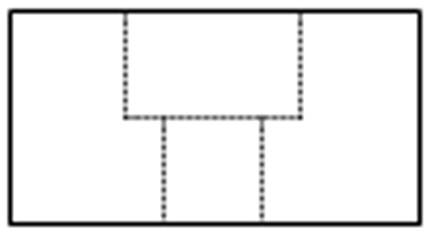 | STEP2HOLE |
(c)  | STEP1POCKET | (d)  | STEP2POCKET |
Groove Features | |||
Feature Diagram | Feature Name | Feature Diagram | Feature Name |
(a) 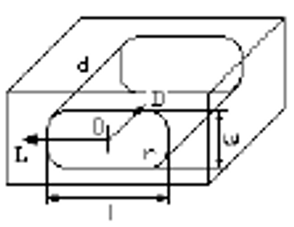 | HOLE_ RECTANGULAR_STRAIGHT | (b) 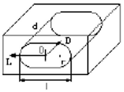 | HOLE_ OBROUND_ STRAIGHT |
(c) 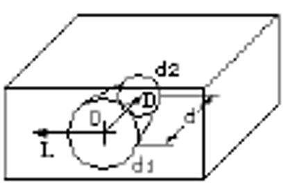 | HOLE_ ROUND_ TAPERED | (d) 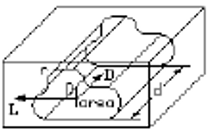 | HOLE_ FREE_SHAPED STRAIGHT |
Cavity Features | |||
Feature Diagram | Feature Name | Feature Diagram | Feature Name |
(a) 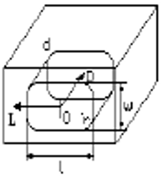 | POCKET_ RECTANGULAR_ STRAIGHT | (b) 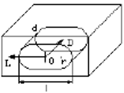 | POCKET_ OBROUND_ STRAIGHT |
(c) 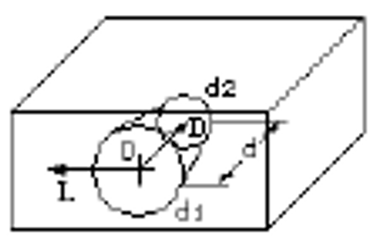 | POCKET_ ROUND_ TAPERED | (d) 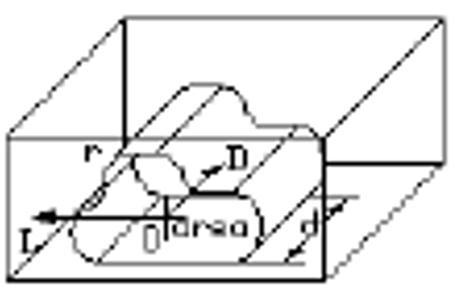 | POCKET_ FREE_SHAPED STRAIGHT |
Edge Step Features | |||
Feature Diagram | Feature Name | Feature Diagram | Feature Name |
(a) 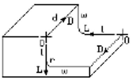 | SIDE_ NOTCH_ RECTANGULAR_ | (b) 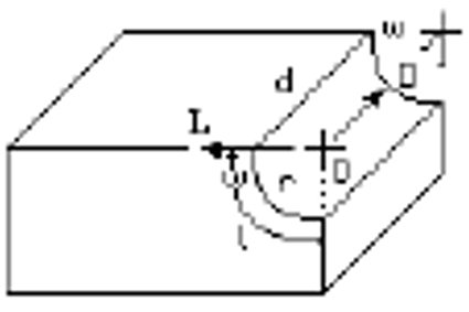 | SIDE_ NOTCH_ ROUND_ CONCAVE_1 |
(c) 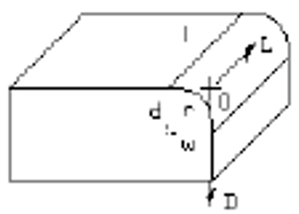 | SIDE_ NOTCH_ ROUND_ CONVEX_2 | (d) 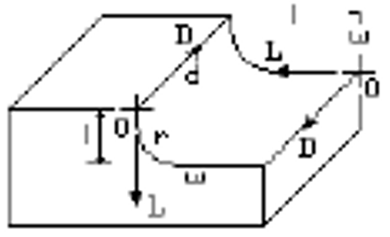 | SIDE_ NOTCH_ U_SHAPED_1 |
Corner Step Features | |||
Feature Diagram | Feature Name | Feature Diagram | Feature Name |
(a) 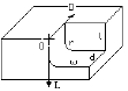 | CORNER_ NOTCH_ RECTANGULAR | (b) 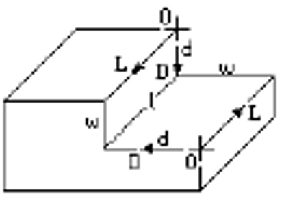 | CORNER_ NOTCH_ STRAIGHT |
(c) 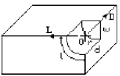 | CORNER_ NOTCH_ ROUND_ CONCAVE | (d) 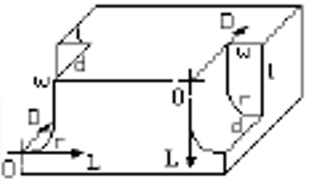 | CORNER_ NOTCH_ U_SHAPED |
Keyway Features | |||
Feature Diagram | Feature Name | Feature Diagram | Feature Name |
(a) 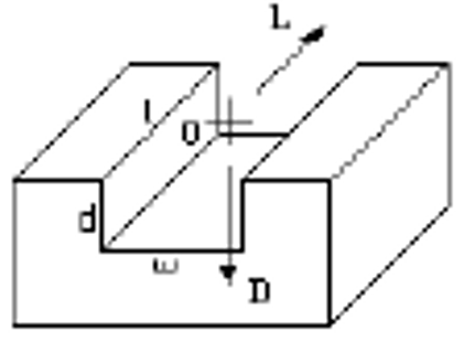 | SLOT_ RECTANGULAR_1 | (b) 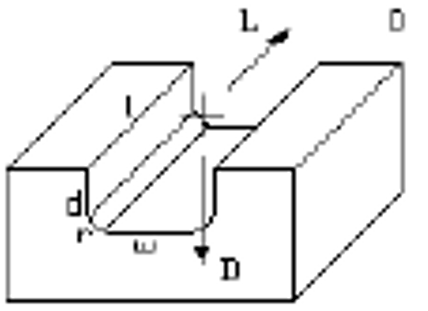 | SLOT_ RECTANGULAR_2 |
(c) 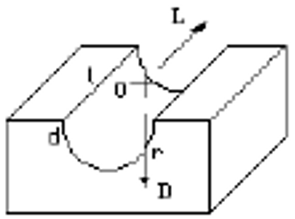 | SLOT_ ROUND_1 | (d) 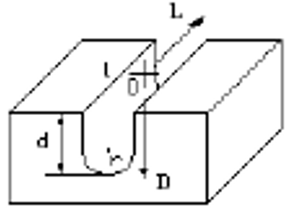 | SLOT_ U_SHAPED_1 |
(e) 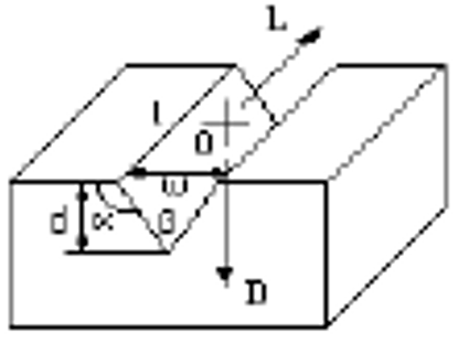 | SLOT_ V_SHAPED | (f) 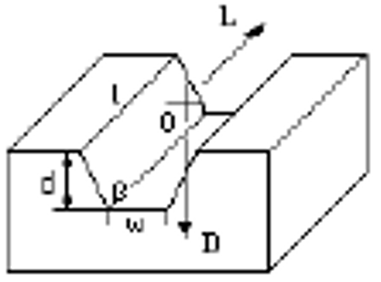 | SLOT_ UPSIDE_DOWN_ DOVE_TAIL |
(g) 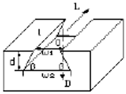 | SLOT_ DOVE_TAIL | (h) 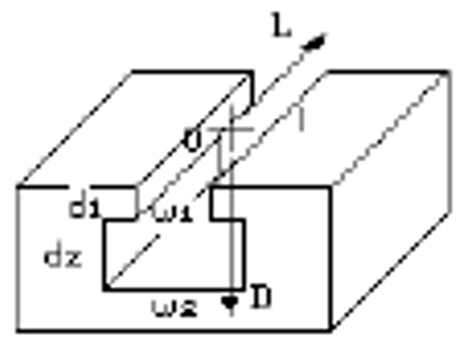 | SLOT_ T_SHAPED |
Plane Features | |||
Feature Diagram | Feature Name | Feature Diagram | Feature Name |
(a) 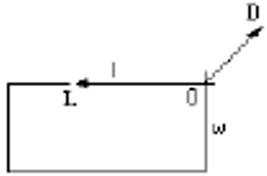 | SURFACE_ PLANAR_ RECTANGULAR | (b) 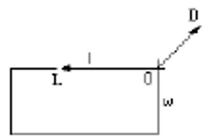 | SURFACE_ PLANAR |
(c) 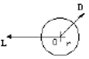 | SURFACE_ PLANAR_ ROUND | ||
Table 14 shows the tool knowledge base stores the basic attributes, types, functions, parameters, and their interrelationships. Through ontology modeling technology, the standardization and structuring of tool data are realized.
Tool | Small B | Small H | L |
Standard Tool | 4h13 | 4h13 | $63 \pm 2$ |
Turning Tool | 4h13 | 4h13 | $80 \pm 2$ |
High-Speed Steel Turning Tool | 5h13 | 5h13 | $63 \pm 2$ |
Square Turning Tool | 5h13 | 5h13 | $80 \pm 2$ |
Rectangular Turning Tool | 6h13 | 6h13 | $63 \pm 2$ |
Round Turning Tool | 6h13 | 6h13 | $80 \pm 2$ |
Irregular Quadrilateral | 6h13 | 6h13 | $100 \pm 2$ |
Welded Turning Tool | 6h13 | 6h13 | $160 \pm 2$ |
Machine-Clamped Turning Tool | 6h13 | 6h13 | $200 \pm 2$ |
Milling Cutter | 8h13 | 8h13 | $63 \pm 2$ |
Drill Bit | 8h13 | 8h13 | $80 \pm 2$ |
Reamer | 8h13 | 8h13 | $100 \pm 2$ |
Boring Tool | 8h13 | 8h13 | $160 \pm 2$ |
Broach | 8h13 | 8h13 | $200 \pm 2$ |
Thread Cutting Tool | 10h13 | 10h13 | $63 \pm 2$ |
Gear Cutting Tool | 10h13 | 10h13 | $80 \pm 2$ |
Shaft Cutting Tool | 10h13 | 10h13 | $100 \pm 2$ |
The machine tool knowledge base stores the basic characteristics, types, structures, functions, and working principles of machine tools are provided in Table 15. Through systematic and structured methods, it provides support for machine tool selection, configuration, maintenance, and optimization.
Machine Tool Name | Max Diameter $\times$ Max Workpiece Length |
Light Horizontal Lathe | $340 \times 1000$ |
Saddle Lathe | $340 \times 750$ |
Vertical Lathe | $360 \times 1000$ |
Wheel Lathe | $400 \times 750$ |
Profiling Lathe | $490 \times 1500$ |
Crankshaft Lathe | $490 \times 2000$ |
CNC Horizontal Lathe | $500 \times 750$ |
Milling Machine | $500 \times 750$ |
Planer | $610 \times 1000$ |
Drilling Machine | $615 \times 3000$ |
Boring Machine | $615 \times 4000$ |
Grinding Machine | $630 \times 1500$ |
Shaper | $630 \times 3000$ |
Sawing Machine | $630 \times 4000$ |
Thread Processing Machine | $660 \times 1000$ |
Gear Processing Machine | $660 \times 1500$ |
Special Machine Tool | $1000 \times 3000$ |
4. Experimental Verification and Result Analysis
This paper uses the process data of an aircraft engine component as experimental data. The data includes information on the component’s processing technology, machine tool selection, tool selection, and other details. By constructing a process ontology model, systematic management of process knowledge is achieved.
Process knowledge modeling, as the core of process knowledge management, can formalize process knowledge through an organizational model and represent it in a computer system. Knowledge is collected and entered into the knowledge base following this structure, enabling the large amount of knowledge accumulated in industrial practices to be digitized and shared. The process knowledge for aircraft engine components is complex and diverse, and the existing discrete process database cannot efficiently support the intelligent generation of processes.
Taking the process knowledge of a long tension bolt for an aircraft engine as an example, the entire process flow can be represented through the ontology modeling meta-language—the five elements constructing an ordered combination of the ontology. In the diagram, each meta-language represents a specific machining operation, such as turning, grinding, gear hobbing, etc., while the ontology meta-language displays how these operations are executed in a specific order. The long tension bolt is the instance, SKU, PKU, and FKU are the concepts, the Parts Machining Chain (PMC) is the relation, the meta-language definition is the axiom, and the expression model is the function. Through this structured expression, process knowledge can be standardized and stored in the process library and facilitates subsequent querying, modification, optimization, and sharing. Below is a detailed explanation of its application example.
To facilitate the effective implementation of process knowledge modeling and management, basic concepts such as SKU, PKU, PMC, and others are briefly defined to provide theoretical support for process knowledge modeling and management.
Definition 1: SKU is basic unit of process knowledge. It is the indivisible knowledge unit in the process knowledge expression and consists of concepts, attributes, and rules of process knowledge. The expression model for SKU is as follows:
where, Process knowledge concept (PKC) represents the basic concept of process knowledge, Process Knowledge Attribute (PKA) represents the attributes of process knowledge, and Process Knowledge Rule (PKR) represents the rules of process knowledge.
Based on the function type of the step, it can be divided into Machining Step Knowledge Units (MSKU) and Inspection Step Knowledge Units (ISKU). The MSKU includes Rough Machining Units (RMU), Semi-finishing Machining Units (SMU), and Finishing Machining Units (FMU); the ISKU includes Dimensional Tolerance knowledge Units (DTU) and Geometric Tolerance knowledge Units (GTU), and their expressions are as follows:
Definition 2: PKU is based on features, with all SKUs corresponding to the feature combined in processing order. It is divided into process knowledge units and inspection process knowledge units. Its expression model is as follows:
where,
Since a PKU is composed of SKUs, it can also be called a process chain. Based on the specific function type of the process chain, it can be divided into MPC and Inspection Process Chains (IPC). The MPC is composed of Rough Machining Units (RMU), Semi-finishing Machining Units (SMU), and Finishing Machining Units (FMU), and its expression is as follows:
The inspection process chain is composed of Dimensional Tolerance knowledge Units (DTU) and Geometric Tolerance knowledge Units (GTU), and its expression is as follows:
Definition 3: PMC consists of all the PKUs for the part, and its expression is as follows:
where, Working Procedure Model (WPM) represents the three-dimensional model between the part’s processes. It is used to visually display the process requirements and results using the integrated 3D model.
If the current blank model of the process cannot identify machining features based on the model elements of the current process model and cannot infer the blank model, two methods are used to build the blank model: (1) Direct modeling using CAD modeling functions, providing some rapid direct modeling methods based on the characteristics of the part model and processing technology, such as bounding box modeling, auxiliary feature parameterized modeling, etc.; (2) Directly import the part blank model, for example, in CNC processing processes, the blank model is used in CAM software, and the manufacturing feature body is obtained by the blank model and the part model together.
In the expression of process knowledge, the SKU is the smallest unit of process knowledge, which contains the concepts, attributes, and rules of process knowledge. The PKU is formed by combining SKUs in a certain order, and the machining chain is composed of a series of process chains. Taking the process knowledge of the long tension bolt part of an aircraft engine as an example, the expressions of these three for specific part process knowledge are shown in Figure 9.
(1) Consistency Checking of Classes and Attributes
Assume there are two classes C1 and C2, and the relationship between them is described by the attribute P, expressed by the formula as follows:
That is, for each instance x in class C1, the value of attribute P(x) should be in class C2.
(2) Class Inheritance Consistency Checking Formula:
If class C1 is a subclass of class C2, namely $\mathrm{C} 1 \subseteq \mathrm{C} 2$, then all instances of C1 should also satisfy the attribute constraints of class C2.
(3) Intersection Consistency Checking
If the intersection $\mathrm{C} 1 \cap \mathrm{C} 2$ of classes C1 and C2 is defined, the result of the intersection should logically be consistent, i.e., it should contain instances that satisfy all constraints.
(4) SAT Solver Formula:
Convert the ontology into a set of description logic formulas and use the SAT solver to check whether the formula is satisfiable. The formula is as follows:
If the formula is unsatisfiable, the ontology is inconsistent.
The experimental results indicate that the proposed ontology-based process knowledge model construction method effectively enhances the shareability and reusability of process knowledge. Compared to traditional methods, this approach demonstrates significant advantages in multiple areas.
Firstly, by introducing ontology technology, the degree of structuring of process knowledge has been significantly improved, making knowledge representation more standardized and less ambiguous. Secondly, the ontology-based knowledge model supports semantic reasoning and associative analysis, which can automatically discover implicit relationships within the process knowledge, further enhancing the utility of the knowledge. Moreover, this method, through modular design, supports flexible combination and extension of process knowledge, making it adaptable to knowledge requirements in different scenarios, thus significantly improving the efficiency of knowledge reuse. Lastly, experimental data show that, compared to traditional document-based or database-based process knowledge management methods, the proposed method performs better in knowledge retrieval efficiency, knowledge updating and maintenance costs, and cross-domain knowledge sharing, providing strong support for the intelligent management and application of process knowledge.
In the specific modeling process, to improve the shareability and reusability of the process ontology, the article proposes a method of constructing application ontologies by extending the basic ontology. This includes defining both the basic process ontology and the application ontology, designing the process ontology knowledge model, and ultimately verifying its feasibility through the MBD-based process model application example for an aircraft engine part.
5. Conclusion
This paper proposes an ontology-based method for constructing process knowledge models for aircraft engine parts, aiming to address issues such as fragmentation, heterogeneity, and insufficient shareability in traditional process knowledge management. By incorporating ontology technology, this method builds a hierarchical, structured process knowledge model that combines top-down and integration approaches, utilizing Bayesian reasoning algorithms and consistency verification algorithms to achieve standardized expression and unified management of process knowledge. The specific contributions are as follows:
(1) The use of ontology description languages (e.g., OWL) to formalize the expression of process knowledge. Through a top-down construction approach, abstract high-level concepts (such as “machining method” and “machine type”) are gradually refined into specific concepts (such as “CNC lathe” and “milling machine”), ensuring the logical and hierarchical structure of the knowledge. The integration approach supplements the specific knowledge content, and the combination of both significantly improves the efficiency of constructing the knowledge model.
(2) The Bayesian reasoning algorithm provides more accurate and reliable process decision support by integrating knowledge from different sources in the process knowledge model. It handles uncertainty, updates prior knowledge, and optimizes process parameters, playing a vital role in complex process design tasks.
(3) Consistency verification algorithms are crucial in the construction of the knowledge ontology, particularly in complex domains (e.g., the aircraft engine process knowledge model). Consistency checks ensure the logical correctness of the ontology, verifying that the defined classes, attributes, and constraints do not have logical conflicts. In the ontology construction process, consistency checking helps identify potential errors and prevents inconsistencies in the model, ensuring its validity.
(4) The consistency check, performed through a reasoning engine, checks whether there are contradictions or illogical parts in the ontology. This allows for syntax consistency verification (checking whether the ontology's syntax adheres to OWL standards) and semantic consistency verification (ensuring no contradictions and that attribute and class definitions are logically coherent).
The experimental results demonstrate that this method effectively enhances the systematic management of process knowledge and provides theoretical support for intelligent process design in aircraft engine parts.
The data used to support the research findings are available from the corresponding author upon request.
The authors declare no conflicts of interest.